
A reliable DMX fountain lighting system starts with a clear addressing and zoning strategy. Each fixture or fixture group must have a defined DMX address, channel requirement, control zone, and physical location before programming begins. For projects using RGB fountain lights, this structure determines whether colors, fades, chases, and synchronized effects can be reproduced consistently across the entire fountain.
The practical design sequence is fixture mapping → DMX addressing → zoning → signal distribution → programming → synchronization → testing. Treating these as separate design stages makes troubleshooting significantly easier and prevents addressing conflicts during commissioning.
DMX512 is a digital control protocol that sends lighting commands from a controller to compatible fixtures. In a fountain installation, the controller can assign individual colors, brightness levels, or programmed effects to different underwater lights according to their DMX addresses.
A typical DMX water fountain system includes a DMX controller, signal distribution equipment where required, DMX-compatible fountain lights, power supplies, and appropriately terminated signal lines.
The key design consideration is that DMX control data and fixture power are separate functions. A lighting fixture may receive power through one circuit while receiving control information through the DMX network.
For RGB fountain lights, the DMX channel configuration determines how the controller addresses red, green, blue, dimming, speed, or other available functions. The exact channel count depends on the fixture's DMX mode.
DMX addresses should be assigned according to both the fixture's channel count and its intended programming role. Every fixture or independently controlled fixture group needs a unique address range when individual control is required.
For example, if an RGB fixture uses three DMX channels, one fixture might occupy addresses 1–3, while the next begins at address 4. If the fixture has additional functions such as dimming or effects, its required channel range will be larger.
Before installation, create a fixture schedule containing:
| Fixture ID | Physical Location | DMX Address | Channel Mode | Control Zone |
|---|---|---|---|---|
| L01 | Fountain Ring A | 001 | RGB | Zone A |
| L02 | Fountain Ring A | 004 | RGB | Zone A |
| L03 | Fountain Ring B | 007 | RGB | Zone B |
| L04 | Fountain Ring B | 010 | RGB | Zone B |
The physical fixture ID should correspond to its position on the fountain drawing. This prevents the common commissioning problem where the software address is correct but the technician cannot identify which physical light it controls.
It is also advisable to reserve address ranges systematically instead of assigning addresses randomly as fixtures are installed.
DMX zones should reflect the fountain's hydraulic and visual structure rather than simply dividing fixtures by cable length.
Useful zoning approaches include:
By fountain ring: Inner, middle, and outer rings can be controlled independently.
By nozzle group: Lights associated with specific nozzle types can form separate zones.
By fountain section: Large installations can be divided into left, center, and right sections or other architectural sections.
By visual effect: Fixtures intended to create synchronized color transitions can share a control group even if they are physically separated.
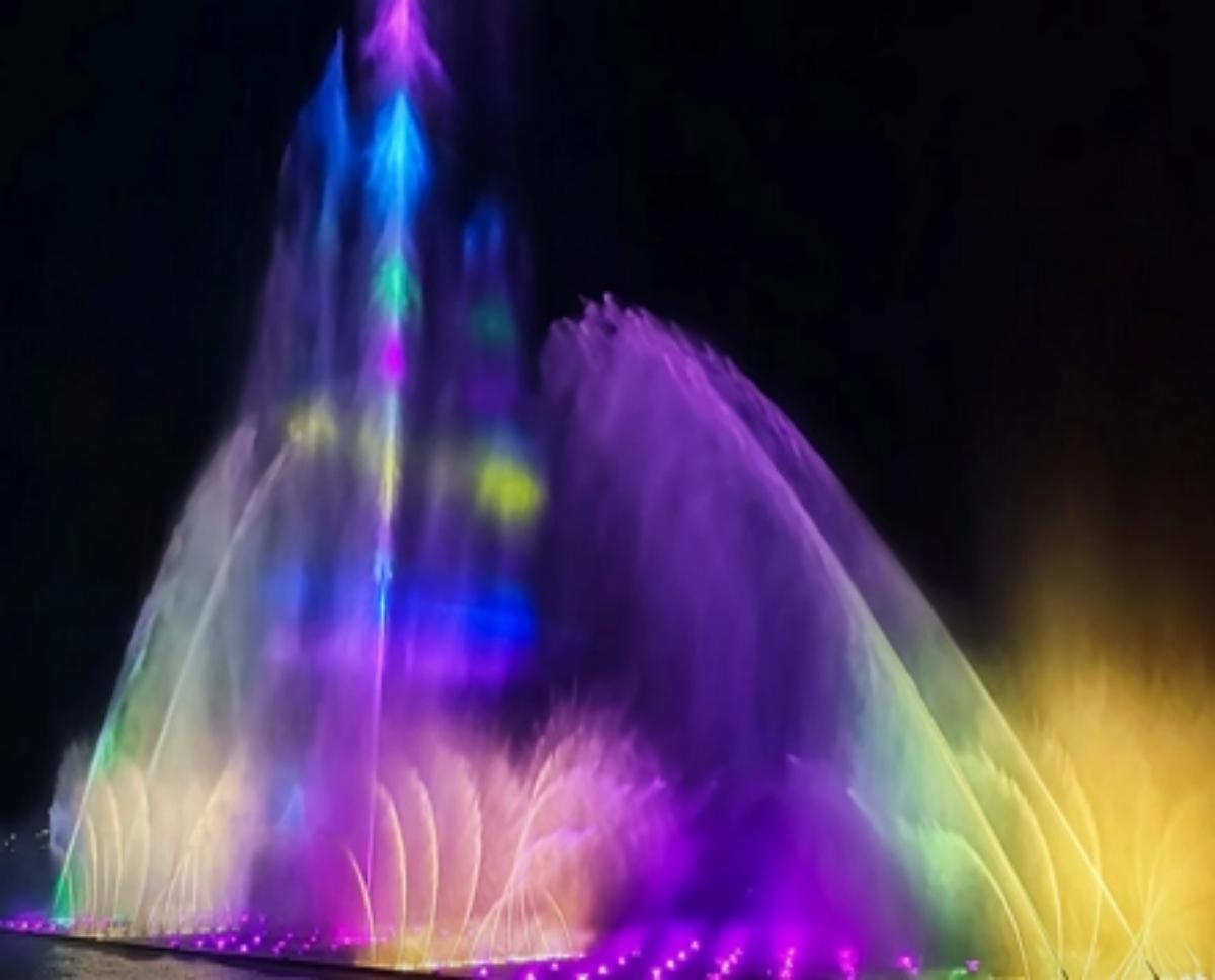
This approach is particularly important for RGB fountain lights because color effects are often designed around water movement. A gradual blue-to-purple transition across a fountain may require several physical areas to behave as one visual zone, while a chasing effect may require adjacent fixtures to remain independently controllable.
The best zoning structure therefore balances physical layout, hydraulic behavior, viewing angles, and show programming requirements.
There is no universal channel count for every RGB fixture. A basic RGB fixture may use separate channels for red, green, and blue, while more advanced models can use additional channels for master dimming, speed, preset effects, or other functions.
Before creating the DMX map, confirm the manufacturer's DMX mode and channel table.
For example:
| DMX Function | Example Channel |
|---|---|
| Red | CH1 |
| Green | CH2 |
| Blue | CH3 |
| Master Dimmer | CH4 |
| Effect/Speed | CH5 |
The actual channel assignment must always follow the fixture's technical documentation.
Incorrect assumptions about channel count can shift every subsequent address and cause multiple fixtures to respond incorrectly. This is one reason fixture schedules should be prepared before final DMX programming.
Synchronization requires the lighting controller to share a reliable timing reference with the fountain show's control system.
For a programmed water display, the sequence may contain several synchronized layers:
Pump or valve operation
Nozzle movement
Water height
Music
RGB lighting changes
Special effects
The lighting sequence should be programmed against the same show timeline used for the fountain effects. For example, a rapid change in water height can be accompanied by a brightness increase, while a slower musical section can use a gradual color transition.
The objective is not simply to make the lights change color at predetermined times. The lighting should reinforce the movement and rhythm of the water.
For large installations, the controller architecture should also consider timing consistency across multiple DMX lines or distributed control nodes. Poorly planned signal distribution can introduce operational problems even when the programming itself is correct.
A large fountain should not be treated as one long uncontrolled DMX cable run. Signal distribution needs to account for cable length, fixture count, physical layout, electrical environment, and access for maintenance.
DMX networks commonly use a daisy-chain topology, with proper termination at the end of each line. Where the installation requires multiple branches or longer distributed runs, DMX splitters or optically isolated distribution equipment can provide a more controlled architecture.
The design should document:
DMX controller location
Signal-line routes
Splitter locations
Maximum cable runs
DMX universe allocation
Fixture addresses
Termination points
Power distribution
Maintenance access
Signal cables should also be routed appropriately to reduce potential interference from power cables and other electrical equipment.
A clean distribution diagram can save substantial commissioning time because technicians can trace a fixture from the control system to its physical location without dismantling unrelated equipment.
Commissioning should proceed systematically rather than starting with the programmed show.
First, verify power to each lighting circuit. Then confirm that every fixture responds to its assigned address and DMX mode. Test individual RGB channels before testing grouped scenes.
A useful commissioning sequence is:
Verify fixture IDs against the installation drawing.
Confirm power supply and operating voltage.
Check DMX cable continuity.
Confirm addresses and channel modes.
Test each fixture individually.
Test each control zone.
Verify color consistency between fixtures.
Test programmed transitions and effects.
Synchronize lighting with water movement.
Run the complete show under normal operating conditions.
If several lights respond simultaneously when they should operate independently, check for duplicate addresses or incorrect channel modes first.
If only fixtures after a particular point fail, investigate the DMX signal path, connectors, termination, or distribution equipment.
The following information can be included in an RFQ or technical submittal to reduce ambiguity between the lighting supplier, fountain contractor, and control-system integrator.
| Specification | Project Requirement |
|---|---|
| Fixture type | DMX-compatible underwater fountain light |
| Light source | RGB / project-specific configuration |
| DMX protocol | DMX512 or specified protocol |
| DMX mode | Manufacturer-defined channel mode |
| Channels per fixture | Specify exact channel count |
| Addressing | Individual / grouped |
| Control zones | Based on fountain layout |
| DMX universe | Specify required allocation |
| Signal distribution | Direct / splitter / distributed nodes |
| Cable | DMX-compatible signal cable |
| Termination | Required at end of DMX line |
| Power supply | Match fixture voltage and load |
| Synchronization | Fountain controller / show controller |
| Programming | Static scenes / dynamic effects / show sequence |
| Commissioning | Individual, zone, and full-show testing |
Providing these details before procurement helps ensure that the selected dmx water fountain lighting system can integrate with the project's existing fountain control architecture.
Effective DMX fountain lighting is primarily a control-system design exercise, not simply a matter of installing programmable lights. Addressing must correspond to the fixture's actual channel configuration, zoning should reflect the fountain's physical and visual structure, and signal distribution must support reliable communication throughout the installation.
For projects using RGB fountain lights, the lighting schedule should be developed alongside the fountain's hydraulic and show-control design. A well-documented DMX map, logical zoning strategy, reliable signal architecture, and coordinated commissioning process provide the foundation for precise color control and repeatable show synchronization.
DMX is a digital lighting-control protocol that allows a controller to send individual commands to compatible fountain lighting fixtures.
Yes. When the fixtures support individual DMX addressing, each light can be programmed independently.
Assign addresses according to each fixture's DMX channel count and create a sequential address map based on the physical fountain layout.
Yes. DMX lighting can be programmed to follow a show timeline and synchronize with music, water movement, and other fountain effects.
Not always. Smaller systems may use a direct DMX chain, while larger or more complex installations may benefit from splitters or distributed signal nodes.
Common causes include duplicate addresses, incorrect DMX modes, damaged signal cables, poor connections, missing termination, or incorrect controller configuration.

 +86-17378775697
  English